
Answers to common questions handled by our support staff, along with
some tips and tricks that we have found useful and presented here as questions.
Note: In these answers we will follow a few shorthand conventions for describing
user-interface procedures. Key combinations will be presented like this: Ctrl+Alt+Delete,
which means that you should press and hold down the Control key, the Alt key, and the
Delete key at the same time. Menu selections will be presented like this: File->Open,
which means that you should open the File menu, and then make the Open selection.
Q: Something's broken and I don't know what. Where do I go from here?
Q: Why are simulations not starting on my Windows 98 machine?
Q: Can I use Desktop Radiance without AutoCAD?
Q: How do I create high-quality renderings? (Short answer)
Q: How do I create high-quality renderings? (Longer answer)
Q: Hints on setting up the rendering parameters? What do they do?
Q: How do I setup up different views?
Q: What do these error messages mean?
warning - (.\lum/lbnl/ies03/ies03.oct): unknown type "mixpict"
fatal -
boundary does not encompass scene
rad: error generating octree
<filename>.oct removed
warning - aiming failure for light source "<filename>_123.abc"
An attempt was made to access drive:\path\<filename>.pic past its end.
Warning - no
light sources found
...
pfilt: picture too dark or too bright
rad: error filtering view <viewname>
<filename_view>.pic removed
(13)Unexpected end of file after reading header-possibly caused by not having an emtpy line after header.
Warning - zero area for polygon "<filename>_123.abc"
Q: What is in the Desktop Radiance created files?
Q: Some of the Desktop Radiance help buttons don't work. How do I get help?
Q: How do I turn the lights off?
Q: Illluminance and Luminance, what's the difference?
Q: Why is my rendering all beige?
Q: Why is the picture washed-out whitish (i.e. like an overexposed photo)?
Q: How do I create a new location?
Q: How do I work with the Desktop Radiance camera in Autocad?
Q: Hints on using boolean operations?
Q: How do I render a plan view?
Q: Why does the North Arrow symbol / Camera Icon appear too small/big?
Q: Why is the "Adjust surface normals" arrow not showing up?
Q: Where is Desktop Radiance getting its glazing data from?
Q: Can I attach 2 materials to a surface, one on the front and one on the back?
Q: Can I import geometry from other 3d modeling programs?
Q: I've imported a drawing into Autocad. What can I do to make it more efficient?
Q: Has Desktop Radiance been validated?
If your question isn't answered here, you can post it on our support newswgroup, http://groups.yahoo.com/group/DesktopRadiance.
A: Something's broken and I don't know what. Where do I go from here?
You can download this test drawing, which is a drawing of
just a flat disk, then follow these steps to see if your installation is stable.
1. Save the attached drawing called "test" to C:\TEMP (or wherever)
2. Open Desktop Radiance from its icon in the Start Menu or Desktop
3. Open the "TEST.DWG" file
4. Go to "Radiance-->Simulation...", press enter in response to the
"select camera" prompt, then type "test1" for the scenario name, then
type "all" for all surface, then press enter to start the synchronization
process.
5. The Camera Simulation Setup dialog box should appear.
Make sure that the time of day is a daytime condition. Make no other changes (we want to
start an interactive simulation) and press "Start"
6. The simulation manager should appear.
Look for an icon on the taskbar to appear called "DOS Shell". If it disappears
before the Winrview window appears, then the installation is broken.
7. When the Winrview window appears, verify that you have a picture of a blue circle.
8. Exit Winrview and allow it to save the image. Make sure that this is saved in
C:\TEMP\TEST
9. The simulation manager should now be at the top, and the "test1" scenario
should be selected. Press Display/analyze. The image you saw previously with Winrview
should reappear with Winimage.
That is the basic test of a proper installation. If this works, so should everything else,
unless you run into one of the known bugs. For example, Desktop Radiance currently only
support one calculation grid, and one reference point per drawing.
Back to FAQs list
A: Why are simulations not starting on my Windows 98 machine?
There are problems with certain versions of Windows98 that cause the simulation to fail. This may be due to a broken pipe() function that will display a variety of error messages. In particular, if you see "gensky" in the DOS Shell window, this is probably the Windows98 pipe() bug. Norton Antivirus with auto protect enabled in win98 prevents oconv and rpict from writing its output to file. Hence it is important to disable Norton Antivirus 2000 so as to run Desktop Radiance without problems. DR can run without problems in computers loaded with McAfee virus protection enabled.
Back to FAQs list
A: Can I use Desktop Radiance without AutoCAD?
The main functionality of Desktop Radiance was designed
to be used within AutoCAD, and can't be operated as a stand-alone. This includes
all editing functions, such as assigning materials, luminaries, etc.
In other words, the user interface part of the package is of little use without
AutoCAD. You can, however, use the underlying Radiance binaries, if you just want
to run your simulations manually (Radiance commands can be started from the
DOS prompt.)
Another way of answering this question is no, Desktop Radiance cannot run without
AutoCAD. But the Radiance program the Desktop Radiance installation saves
onto your computer can be run without AutoCAD.
If you need more control but have reservations about working in text only
mode, you might want to look into one of the commercial alternatives.
Back to FAQs list
A: How do I create high-quality renderings? (Short answer)
The interactive rending program (rview) is intended as a preview tool to validate your model and rendering parameters. Once you are satisfied with the integrity of the rendering, you will need to create a batch simulation in order obtain high-quality results. A batch job can render images at resolutions far greater than your screen resolution. From the Simulation Manager, click "duplicate", provide a name for the scenario, and then click on "advanced" from the bottom of the Simulation Setup dialog box. Click on the "Rendering" tab and enter the final resolution you want for your image in the "resolution" fields. Then select the amount of over-sampling you would like. Be careful, each increment (for example, 1x -> 2x) potentially quadruples the rendering time. Over-sampling reduces the "jaggies".
Back to FAQs list
A: How do I create high-quality renderings? (Longer answers)
The interactive renderer (rview) is not meant to generate high-quality images (see previous FAQ). Changing the paremeters during rview will make the rendering slow and the high and accurate settings are unlikely to be reflected. Use rview to preview and validate your model, not for generating final renderings!
Alternate Approach #1: Let the program figure it out:
Click on the "Advanced" button on the simulation manager
to reach the "Advanced Calculation Parameters" dialog box. In there are 4 tabs:
Analysis, Lighting, Geometry, and Rendering.
Click on the Lighting tab and check "high" button for Lighting Variability. And,
check the box "Keep ambient data".
Click on the Geometry tab and check "high" button for Geometric Detail.
And, although there is a "high" Render Quality option on the Render tab, it's
recommanded that it be kept at "medium". A "high" setting here is very
costly.
Next, close the dialog box and start the rendering in batch mode.
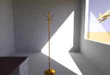
The following images were rendered (in most parts) per the above
method. "High" on the Lighting and Geometry tabs under the Advanced button and
"medium" under the Render tab. However, the image on the left has the box
"Keep ambient data" unchecked while the right has it checked. With the exception
of -av (ambient value), -ps (pixel sample) and -ab (ambient bounce), the parameters were
determined by Desktop Radiance.
Can you spot at least 6 differences between the two pictures? (Images
may appear identical on less than "true color" monitors)
LEFT Image Parameters as determined by Desktop Radiance: -dp 1024 -ar 14 -ms 0.6 -ds .3 -dt .1 -dc .5 -dr 1 -sj .7 -st .1 -aa .15 -ad 768 -as 196 -lr 6 -lw .002 -av 0 0 0 -ps 2 -ab 2
RIGHT Image Parameters as determined by Desktop Radiance: -dp 1024 -ar 14 -ms 0.6 -ds .3 -dt .1 -dc .5 -dr 1 -sj .7 -st .1 -af room.amb -aa .15 -ad 768 -as 196 -lr 6 -lw .002 -av 0 0 0 -ps 2 -ab 2
Note: Depending on your monitor's capabilities, the following images may all seem low quality!
Alternate approach #2: Self-diagnose the problem then try to find a resonable rendering parameter for it here.
Alternate approach #3: Check out the PDF documents presenteded by Dr. Mardaljevic at the 2003 Radiance Workshop. The PDFs covers more information than just rendering parameters.
Here is an example bad rendering and ways to make it better. (The settings are extremely crude, the parameters are not the defaults for Desktop Radiance):
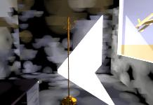
Original Parameters: -ar 7 -ms 1.2 -ps 2 -pt 0.150 -dt 0.10 -dc 0.250 -dj 0.0 -ds 0.0 -dr 0 -dp 128 -sj 1.0 -st 0.30 -av 0.0 0.0 0.0 -ab 1 -aa 0.20 -ad 12 -as 0 -lr 4 -lw 0.010
The above room is a low-quality rendering. To get rid of the black
blotches on the walls, adjust some/all of the -a* parameters, -aa, -ab, -ad, -ar,
-as, and/or -av.
By increasing -ad (ambient divisions) from 12 to 128 and keeping the others parameters the
same, we get the following image. Notice the big black blotches are gone but still the
ground and walls seem rough.
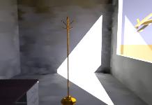
Parameters used: -ar 7 -ms 1.2 -ps 2 -pt 0.150 -dt 0.10 -dc 0.250 -dj 0.0 -ds 0.0 -dr 0 -dp 128 -sj 1.0 -st 0.30 -av 0.0 0.0 0.0 -ab 1 -aa 0.20 -ad 128 -as 0 -lr 4 -lw 0.010
Next
, if the -as (ambient supersample) is increased from 0 to 64 (half of -ad), the walls and the ground become more refined.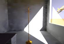
Parameters used: -ar 7 -ms 1.2 -ps 2 -pt 0.150 -dt 0.10 -dc 0.250 -dj 0.0 -ds 0.0 -dr 0 -dp 128 -sj 1.0 -st 0.30 -av 0.0 0.0 0.0 -ab 1 -aa 0.20 -ad 128 -as 64 -lr 4 -lw 0.010
For the next image, I increased -ab (ambient bounce) from 1 to 2, and now the corners are illuminated.
Parameters used: -ar 7 -ms 1.2 -ps 2 -pt 0.150 -dt 0.10 -dc 0.250 -dj 0.0 -ds 0.0 -dr 0 -dp 128 -sj 1.0 -st 0.30 -av 0.0 0.0 0.0 -ab 2 -aa 0.20 -ad 128 -as 64-lr 4 -lw 0.010
For this next image, I raised -ar (ambient resolution) from 7 to 14, -ad (ambient division) from 128 to 256, and -ds (source substructuring) from 0 to .3.
Parameters used: -ar 14 -ms 1.2 -ps 2 -pt 0.150 -dt 0.10 -dc 0.250 -dj 0.0 -ds 0.3 -dr 0 -dp 128 -sj 1.0 -st 0.30 -av 0.0 0.0 0.0 - ab 2 -aa 0.20 -ad 256 -as 64 -lr 4 -lw 0.010
So, by manually changing certain parameters, a decent batch rendered image can be had.
A: Hints on setting up the rendering parameters? What do they do?
Click here for online table of rendering parameters and other useful information. You may also want to take a look at A: How do I create high-quality renderings? (Longer answer)
Back to FAQs list
A: With -ab 0, why does the sun illuminate the surfaces in the room (i.e. sun patch), but not the sky, although I can see both through the opening?
This has to do with the way Radiance works with different types of light sources. The sun is modeled as a "source", which is dealt with by Radiance's direct lighting calculation. It turns out to be very easy to determine whether or not a surface is directly illuminated by a source, so this is done very quickly. This is done even with -ab 0. The sky is modeled as "glow", so it will only take part in Radiance's indirect lighting (i.e. interreflection) calculation, which is only performed for values of -ab greater than zero. This involves the process of generating extra rays at each intersection of a ray with a surface and checking if any of them will hit the "glow" source (or any other source, or an illuminated surface). The higher the value of -ab, the more subsequent reflections will be considered.
Back to FAQs list
A: How do I setup different views?
If you are not comfortable
with setting up the camera (icon) in the drawing,
you can more easily set up a view from within
the interactive viewer (winrview). After you
create a view in the interactive viewer, save the
view and add it to the rif file, and then subsequent
renderings based on the same scenerio will be able to
use the view that has been created.
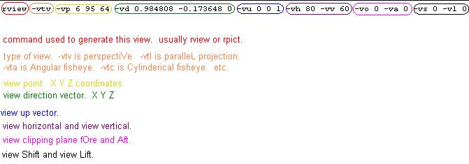
Possible View Types - what do they mean and what do they do:
"Angular fisheye" - The distance from
the center of the image is proportional to the angle from the central view
direction.
Viewpoint, Direction, and Up - how to set these:
View Point -
where you are viewing from. Input X, Y, and Z coordinates.
View Size Horizontal and Vertical - how to set these:
Angular fisheye - Measured in degrees, maximum angle allowed is 360.
View Clipping Plane, Fore and Aft - how to set these:
Fore - the number entered will be the distance away
from the View Point for the Fore Clipping Plane.
View Offset, Horizontal and Vertical - how to set these:
(This is complicated. To be explained later.)
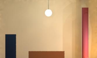
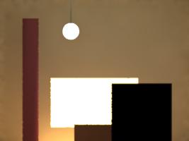
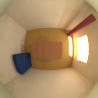
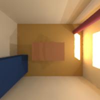
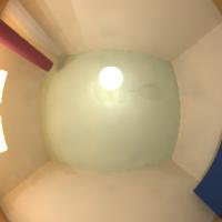
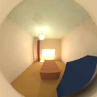
Here are different views of the room.
Following each image are the parameters used to generate the image.
Back to FAQs list A: What do these error messages mean? warning -
(.\lum/lbnl/ies03/ies03.oct): unknown type "mixpict" fatal - boundary
does not encompass scene An attempt was made to access
drive:\path\<filename>.pic past its end. (13)Unexpected end of file
after reading header-possibly caused by not having an emtpy line after Back to FAQs list A: What is in the
Desktop Radiance created files? The following file extensions are created by
Desktop Radiance. When needed (and if possible) you should name your
files accordingly. (Just like you wouldn't save a Microsoft Word
document with a .xls extension) To rename the drawing for a project, select from the file menu
FILE>SAVE AS and rename the drawing. You do not need to rename the project file, it
will not renamed but it will automatically be associated with the new drawing name. To
rename the drawing file and the project file, first rename the drawing. Go to FILE>SAVE
AS and rename the drawing. Then close the Graphic Editor or AutoCAD program. From Windows
explorer find the project file and delete it. Also delete the old drawing files and backup
drawings. Then back in the drawing file go to Radiance>Simulation>Camera, select a
camera. A dialog box will appear that says the project file can't be found. Click OK and
it will take you to the open dialog box. Click ok to create a project file with the same
name as your drawing file. A: Some of the Desktop
Radiance help buttons don't work. How do I get help? The Desktop Radiance Help file is installed in the Desktop Radiance
help directory and may be accessed in windows by double clicking on the Dradhelp.hlp icon
(purple book). Specify a time in the simulation setup that corresponds to a night
time condition. A: How do I turn the
lights off? Change the "percent dimming (lumens)" and
"percent dimming (watts)" values to 0. This is accessed through the Luminaire
Properties dialog box. A: Illuminance and Luminance,
what's the difference?
Illuminance is measured in lux (lumens/m^2) or foot-candles (lumens/ft^2). A: Why is my rendering all
beige? What you are seeing is probably the default ground in a plan view.
Click on the V (view) icon while in the interactive renderer and see if the Z coordinate
for view direction is zero. If it is, change it to something bigger than zero and you
should be able to see something else. A: Why is the picture
washed-out whitish (i.e. like an overexposed photo)? Probably because your Radiance image contains true values of
luminance or illuminance and not scaled to your output device. You can adjust the
exposure (which does not affect the underlying values, just the display for your
monitor) or use pcond to scale pictures to your output device (which will "flatten" the
values). For more information on pcond, please read the
pcond man page.
A: How do I create a
new location? The following applies to version 1.02. Provide a City name. It does not have to be an actual location.
Whatever is entered for the new location is added into the project database. Country and
State fields are optional. Turbidity characterizes the opacity of the atomosphere. Greater
turbidity factors correspond to greater atmospheric scattering. A turbidity factor of 1.0
indicates an ideal, clear, fully dry atmosphere. Values less than 1.0 are physically
impossible. The CIE standard value for Turbidity is 2.0 (very clear sky) and the generally
the maxium is 6.0 (very hazy, polluted sky). Click here for a site which
allows you to input a location (Europe and surrounding areas only) and outputs turbidity
factors. Desktop Radiance uses the CIE default of 2.0 for turbidity factor. A: How do I work with the
Desktop Radiance camera in Autocad? There are several ways to manipulate camera pitch both inside and
outside of AutoCAD. Inside AutoCAD, you can use the "DVIEW" command to adjust
the camera aiming. Please see the AutoCAD help system for more information on how DVIEW
works...it is quite complex. The trick with this technique is that the modified view must
be saved "on top of" the older named view using the "DDVIEW" command.
Select the view you have edited, click "new..." and then specify a camera name
that is identical to the camera you just edited. Click "Save View", then
"Redefine" to overwrite the previous definition of that camera. The camera icon
will not update to reflect the new camera properties becuase it exists indepently from the
internal data structures which keep track of AutoCAD views. When you start the next
simulation, be sure to select the camera icon. Outside of AutoCAD, you can use the the
interactive rendering program to manipulate camera settings. There is a toolbar slider
called "pitch" which will adjust the pitch and immediately redraw the new view.
The "Set view" dialog box can be reached using the "Set-->view"
menu command or by clicking on the "V" toolbar icon. The "view
direction" vector is what you will need to edit. This is by far the most difficult
method. One additional method also using the "Set view" dialog box is to edit
the "view shift" parameter. Specify the decimal percent above (positive) or
below (negative) you want the view to be oriented. This provides the very pleasing effect
of looking up without introducing severe 3-point perspective distortion. This is
equivalent to using a slip-lens camera. The vertical lines remain vertical in the image.
Whichever way you work with the interactive rendering program, to make the camera/view
changes accessible in subsequent scenarios, you need to use "File-->Append view to
RIF file". RIF files are named after the scenario name. A scenario which is
duplicated from the scenario you updated with a new view will show the additional view(s)
you created in the "Camera Simulaiton Setup" dialog box in the
"Camera" drop-down list. We are currently working on a "Camera
Properties" dialog box which will bridge this gap between AutoCAD views and Desktop
Radiance cameras. It will provide a real-time wireframe representation of your view and
cause the camera icon to update itself appropriately. Note: If you find the dview command in AutoCAD hard to work with, it
may be easier to remove and reinsert another camera or to adjust the view in the
interactive renderer. For more information on adjusting views in the
interactive renderer, see the FAQ on
How do I set up different views? A: Hints on using
boolean operations?
1. Save the ACAD drawing, booleans and all, in either the regular .dwg format
or as a .dxf.
See also FAQ topics: Can I import geometry from other
3D modeling programs? A: How do I render a
plan view? How to setup a plan view while in Autocad: A: Why does the North
Arrow symbol / Camera Icon appear too small/big? You can go to Radiance ->Preferences and change the Drawing
Scale. To increase the size of the North arrow or the Camera Icon, fill in the drawing
scale box with a number higher than one. If you put five, the north arrow or Camera Icon
will be five times as big as before. If you want the North arrow or Camera Icon to appear
smaller, enter a value that is lower than 1. So, a value of .1 would make the North arrow
or Camera Icon 1/10 the size it was before. After changing the drawing scale value, click
OK. The symbols will appear smaller or larger according to the adjustments made. A: Why is the
"adjust surface normal" arrow not showing up? There are two possible causes. A: How can the tool
"Show Properties" highlight a particular object that's co-linear
w/another object? Co-linear means 2 or more surfaces are sharing an edge. For
example, a corner where a wall and ceiling meet is where they are co-linear.
Because the "show properties" can only show one property at one time, you need
to be aware which object is being picked. AutoCAD provides a mechanism called
"cycling" which allows the user graphically to select and deselect objects. Start from Radiance->Tools->Show Properties-> A: My windows/glazings
aren't contributing as much light as I think they should. What could be wrong with them? There are 2 possible causes. To model a window correctly, make sure
the surface normal of the glazing is pointing inwards. This is because a glazing is
treated as a secondary lightsource, an "illum". (English translation:
"A surface through which or by which large quantities of light are directed".)
If the surface normal is pointing out of the room, you will still be able to see the view
and the sun outside, but the light contribution from outside will not be accurately
accounted for inside the model. Check the glazing surface normals by using the radiance
tool, Radiance-->Tools-->Adjust Surface Normals. Also, make sure the glazing is modeled as a single surface. Having
two panes of glass close together does not simulate a double-pane glazing! All of the
glazings in the Desktop Radiance Library are meant to be attached to single surfaces only,
regardless of their real life counterparts (See also FAQ:
Where is Desktop Radiance getting its glazing data from?). A: Where is Desktop
Radiance getting its glazing data from? Glazing data in the Desktop Radiance library were imported from
Optics 5, a glazing program, which uses data from the NFRC. For more information about
Optics 5, click here. A: Can I attach 2
materials to a surface, one on the front and one on the back? No, a surface in Desktop Radiance is considered to be infinitely
thin and can only have one material attached to it. And, unlike some other modeling
programs, the "back" side of a surface does not appear black. A: Does it matter
which way surfaces face, i.e. if a polygon is defined clockwise or counter-clockwise? For opaque surfaces, no, it does not matter. The surface will have
the same material on both sides. A: Can I import geometry
from other 3d modeling programs? Yes, importing of geometry into AutoCAD works, but objects may not
appear the way you expect. I've exported from FormZ and 3d Studio but mostly with formZ...
AutoCAD accepts files in dxf or dwg format, maybe even others but I've not tried. Light
sources, cameras, animation paths, etc, will not export and will be ignored. Keep in mind
that if you have a large formZ drawing with many polygons, the polygon count will GROW by
many times when in AutoCAD because of triangulation. AutoCAD and Desktop Radiance may have
trouble handling all of the pieces at the same time. After the geometry is imported,
materials may be attached as usual and a rendering started. Depending on how fast your
computer is, waiting for the rendering to start may take awhile too. A: I've imported a
drawing into Autocad. What can I do to make it more efficient? You can replace some of the triangulated surfaces by drawing over
them with 3dfaces or replace faceted spheres, cylinders, and boxes with simple ACIS
solids. If you do draw over existing geometry with 3dfaces or other surfaces, put these
entities in a layer different than the existing geometry. Then, make sure that when you
render, to turn off the layers of the original geometry. Leaving those layers on can
sometimes effect the appearance of the surfaces you created. A: Has Desktop Radiance
been validated? Radiance has been validated by numerous people over the years.
Some of these reports can be found on the Radiance web site under the Reference and
WWW sections. In particular, take a look at the work by John Mardeljevic
http://www.iesd.dmu.ac.uk/~jm/zxcv-thesis
for research on the accuracy of the daylighting calculations as compared to the CIE clear
and overcast sky models.
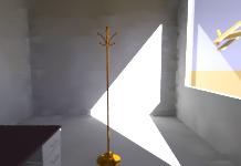
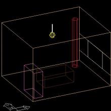
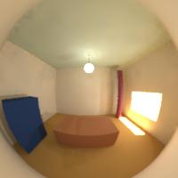
Here a simple Desktop Radiance room.
It is 15 wide x 12 long x 11 high, with an opening in one wall, and
miscellaneous objects inside.
"Cylindrical fisheye" - Like a
standard perspective vertically, but projected on a cylinder
horizontally (like a soupcan's-eye view).
"Hemispherical fisheye" - It's a
projection of the hemisphere onto a circle.
"Parallel projection" - standard parallel.
"Perspective" - standard perspective.
NOTE: View Type affects Viewsize Horizontal and Viewsize Vertical!!
View Direction -
the direction vector of where you are looking to. Input X, Y, and
Z vectors. Example, if you are looking towards the zenith of the sky, input 0 0 1.
View Up - the
"up" vector of your image. Input X, Y, and Z vectors. View Up is a
vector pointing perpendicular to your View Direction and points toward
the top of your image. It is roughly equivalent to gravitational up,
but can be different if you want to render an image as if your head is
tilted to the left or right.
Ccylindrical fisheye - Measured in degrees, angles must be smaller
than 180 (cannot equal).
Hemispherical fisheye - Measured in degrees, angles must be 180 or less.
Parallel Projection - Measured in world units, as big as you need.
Perspective - Measured by degrees, angles must be smaller than 180
(cannot equal).
Aft - numbber entered for will be the distance away
from the View Point for the Aft Clipping Plane.
 Plan
Plan
-vtl -vp 7.5 6 8 -vd 0 0 -1 -vu 0 1 0 -vh 15 -vv 12 -vo 0 -va 0 -vs 0 -vl 0
parallel projection plan. The View Point is at center of the room (room is 15 wide x 12 long,
so center is 7.5x6 with height at 8 below the ceiling, above the luminaire).
View Direction vector is down (0 0 -1).
View Horizontal and Vertical 15x12 (size of the room).
 Ceiling Plan
-vtl -vp 7.5 6 7 -vd 0 0 1 -vu 0 1 0 -vh 15 -vv 12 -vo 0 -va 0 -vs 0 -vl 0
Similar setup as a parallel projection plan except the View Direction vector is now looking up (0 0 1).
 Section Elevation X-X
-vtl -vp 7.5 1 5.5 -vd 0 1 0 -vu 0 0 1 -vh 15 -vv 9 -vo 0 -va 0 -vs 0 -vl 0
The View Point is centered along the X-axis (15/2=7.5), 1 unit away from the wall and at 5.5 high.
View Direction is towards positive Y (0 1 0).
View Horizontal is the horizontal size of the room (15 wide), View Vertical is the height of the room (9).
 Section Elevation Y-Y
-vtl -vp 1 6 5.5 -vd 1 0 0 -vu 0 0 1 -vh 12 -vv 9 -vo 0 -va 0 -vs 0 -vl 0
Similar setup as Section Elevation X-X (view point centered close to the appropriate wall).
View Direction is now facing towards positive X (1 0 0).
View Horizontal is now the length of the room (12), View Vertical is still the height of the room (9).
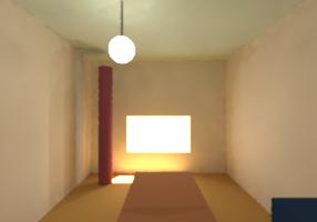 Perspective looking towards +X
-vtv -vp 1 6 5.5 -vd 1 0 0 -vu 0 0 1 -vh 90 -vv 70 -vo 0 -va 0 -vs 0 -vl 0
Similar setup as the Section Elevation X-X except this is a perspective (-vtv), and the View
Horizontal and Vertical numbers needs to be changed to angles. In this case 90 degrees
horizontal and 70 degrees vertical looks nice. The angles have to be smaller than 180 degrees.
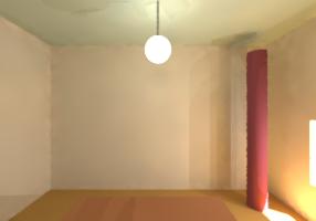 Perspective looking towards +Y
-vtv -vp 7.5 1 5.5 -vd 0 1 0 -vu 0 0 1 -vh 90 -vv 70 -vo 0 -va 0 -vs 0 -vl 0
Similar setup as previous except the View Direction has changed to face +Y.
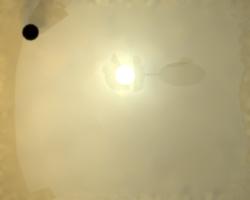
 Fisheye view down
-vta -vp 7.5 6 7.4 -vd 0 0 -1 -vu 0 1 0 -vh 180 -vv 180 -vo 0 -va 0 -vs 0 -vl 0
Angular fisheye view (-vta). The View Point is centered and hanging a bit below the luminaire.
View
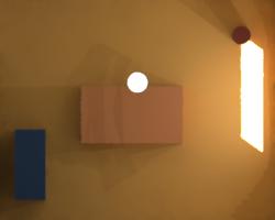
 Perspective Plan
-vtv -vp 7.5 6 8 -vd 0 0 -1 -vu 0 1 0 -vh 110 -vv 110 -vo 0 -va 0 -vs 0 -vl 0
Looking towards the floor, View Point is a little below the luminaire fixture,
with View Horizontal and Vertical angles both 110 degrees.
 Fisheye view up
-vta -vp 7.5 6 5 -vd 0 0 1 -vu 0 1 0 -vh 180 -vv 180 -vo 0 -va 0 -vs 0 -vl 0
Similar to Fisheye View down, except the View Up direction vector is 0 0 1 (up).
 Fisheye looking towards +X
-vta -vp 1 6 5.5 -vd 1 0 0 -vu 0 0 1 -vh 180 -vv 180 -vo 0 -va 0 -vs 0 -vl 0
Similar to the Perspective view towards +X, except the View Type is
Angular (-vta).
 Fisheye looking towards +Y
-vta -vp 7.5 1 5.5 -vd 0 1 0 -vu 0 0 1 -vh 180 -vv 180 -vo 0 -va 0 -vs 0 -vl 0
Simiar to the Perspective view toward +Y, except the View Type is
Angular (-vta).
The mixpict
warning comes up ever-so-often. It can be safely ignored.
rad: error generating octree
<filename>.oct removed
The boundary error happens when any glazing surface is created beyond the
maximum boundary of the scene minus any glazings. If any glazing happens to be
"outside" of the bounding box (the maximal cube required to completely enclose
the scene) of the scene minus glazings, then oconv will fail when it attempts to build an
octree. A workaround is to place some arbitrary non-glazing geometry in the scene, farther
out then the glazing so that the maxium bounding box will encompass the glazing.
warning - aiming failure for
light source "<filename>_123.abc"
This error means when a "shadow" ray, a.k.a., a ray traced by Radiance toward
the light source to determine if the light source is visible, can not find the light
source surface it is expecting to find. Shadow rays are always traced toward the centroid
of the light source surface. If there is a "defect" in the design of the
surface, then an aiming failure will occur. The list of possible defects includes concave
polygons where the centroid is outside of the boundary of the polygon, polygons with
holes, "thin" cylinders where the diameter is greater than the length, and a
disk with a hole (a ring with non-zero inner radius). Note: all of these are perfectly
fine surfaces if the material associated with them is NOT a
light source.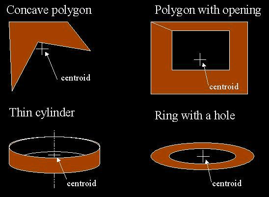
NOTE: A much more rare type of light source aiming failure may occur if the scene
contains two or more overlapping, co-planar surfaces, one or more of which is a light
source. The reason for this defect is because the ray tracing process can only detect
surfaces that are greater than 0.0005 (Radiance's FTINY) world coordinate units apart.
This fudge factor allows rays to "go through" a transparent surface without
running into the same surface it previously intersected.
This error means the
picture is either incomplete or has errors. If you believe the image is complete (the
error is in error), you may forward it to deskrad@floyd.lbl.gov
for help.
Warning - no light sources
found.
...
pfilt: picture too dark or too bright
rad: error filtering view <viewname>
<filename_view>.pic removed.
This means your simulation was of a night-time scene without
luminaires. No final image is created.
header.
The rendered image is either incomplete or has errors. If you believe the image is
complete (the error is in error), you may forward it to deskrad@floyd.lbl.gov for help.
Warning - zero area for polygon
"<filename>_123.abc".
This error usually occurs with geometry that is imported into
ACAD/Desktop Radiance from other 3D modeling programs. It means the vertices of this
polygon don't close or cross and does not make up a valid surface. If you have excessive
zero area warnings for your simulation, it may be a good idea to re-export the geometry
from the other 3D modeling program.
Many Desktop Radiance created files can be opened and manually edited
with wordpad/notepad.
If your windows display is set to hide file extensions for known file
types, you will not see any of these.
For more information on how to show all
file extensions, open up a windows explorer and goto File Options
under the View menu.
scene= lists out the geometry files;
material= lists out the materials to be used;
view= lists all the saved views in your
Desktop Radiance drawing;
and others.
Note that the
render= line is where you can input the
over-ride rendering options (parameters) for your simulations.
Luminance is measured in candela/m^2 (lumens/meter^2/steradian).
Illuminance
Luminance
This article
"Brightness, Luminance, and Confusion" may help explain the
difference in more detail.
(Originally posted in Desktop Radiance discussion group)
From the pulldown Location box, select "New..." and the following dialog box
should appear.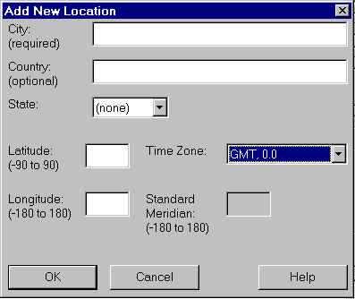
Provide Latitude and longitude in decimal form. Locations south of the Equator are
negative latitudes and locations east of Greenwich(GMT) are negative longitudes. For
example, Athens-Greece would be approximately Lat 37.9 and Long. -23.7.
Select a Time zone the location you are simulating. for Athens-Greece during daylight
savings it is EEST, otherwise it is EET. If you do not know which timezone the new
location is or if it is not on the pull down list, select "Other..." and specify
the Standard Meridian.
Standard Meridian is the longitude of the middle of your time zone. (GMT)-((your
time)*15)=Standard Meridian. For Athens-Greece, it's -2*15, so the Standard Meridian is
-30.
(Originally posted in Desktop Radiance
discussion group)
HOWEVER, if you have
an ACAD drawing modeled with booleans, all is not lost. Here is a "work-around":
2. Open the ACAD drawing in another 3D modeling program, i.e. Form-Z or 3D-Studio.
As the non-ACAD 3D modeling program opens and saves the ACAD drawing,
it will tranform the boolean'ed volumes into acceptable polyface, 3dmeshes,
or 3dfaces.
3. Save the drawing back as an ACAD .dwg file with another name (don't overwrite the
original) after opening it with the "other" 3D modeling program.
Now the .dwg file will have no boolean entities but instead have surface enties.
I've Imported a drawing
into AutoCAD. What can I do to make it more efficient?
Before starting a simulation, make sure your drawing is being viewed as plan view (world
coordinates). Then set elevation (Z) to something bigger than 0. Then when prompted to
select a camera for simulation and the default=current, press enter. When you don't select
a camera while your drawing is in plan view, the default view is current and current is
plan. Next when a simulation starts you will have a plan view.
How to setup a plan view while in the interactive viewer:
Click the V button to reach the "set view" dialog box.
Select Type = Parallel.
Set Viewpoint X and Y as center of drawing. Z as height to start looking down.
Set Direction X = 0, Y = 0, Z = -1. (Looking down).
Set Up X = 0, Y = 1, Z = 0.
Set Size Horizontal and Vertical as the X and Y size of Autocad scene.
Then click ok.
If the interactive view is now showing a plan view, you may save the view definition and
re-use it for later simulations.
1. The scaling of the drawing may be a lot bigger than the scale of the arrow which makes
the arrow hard to see. Or,
2. You may be checking the surface normal of something Desktop Radiance can't figure the
front/back of. ACIS solids (spheres, boxes, cones, and cylinders) are assumed to have
surface normals pointing outward. If an ACIS solid is exploded or boolean'ed, its
component parts (regions, body, etc) will also have no front/back according to our tool,
but will have surface normals pointing outwards.
Note: Surface normals in Desktop Radiance does not matter for opaque materials.
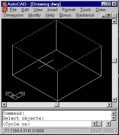

And at the prompt, Select objects: ctrl+left mouse click on where the surfaces are
co-linear. If the highlighted surface is the one you wish to show properties of, press
enter. If you want to show properties of the other object, let go of the control key and
left click again. This time the other co-linear surface should be highlighted. Press enter
to show properties of this other surface.
For transparent/transluscent/clear surfaces and light
sources, yes, it does matter.
ACIS Solids have only limited support in Desktop Radiance.
To transform ACIS solids (including boolean operations) to 3dfaces:
1. In AutoCAD export your drawing in 3ds (3dstudio) format.
(File->Export->3ds)
2. Open a New AutoCAD drawing.(File->New)
3. Insert the 3ds file (Insert->3ds)
4. Save your file.
You will receive a triangulated (3dfaces) version of your project, suitable for Desktop Radiance.
It works fine with both AutoCAD 14 and 2000. Note that you don't need the 3dStudio program at all
One of the most critical evaluations of Radiance can be found in a Russian paper by
Andrei Khodulev and Edward Kopylov. Physically Accurate Lighting Simulation in Computer
Graphics Software,
http://www.integra.co.jp/eng/papers/pals. As is true of all Radiance users, the
authors were still learning the software when they conducted the research. And so,
they conclude that Specter is a better program overall. The images
easily could have improved with slightly higher accuracy parameters.
Here are some others:
Houser, K.W., D.K. Tiller, and I.C. Pasini, "Toward the Accuracy of Lighting
Simulations in Physically Based Computer Graphics Software",Journal of the
Illuminating Engineering Society, vol. 28, no 1, Winter 1999, 117-129.
Ubbelohde, M.S. and Humann, C. "Comparative Evaluation of FourDaylighting
Software Programs", 1998 ACEEE Summer Study on Energy Efficiency in Buildings
Proceedings. American Council for an Energy-Efficient Economy, 1998.
Grynberg, A.,"Validation of Radiance", LBID 1575, LBL Technical Information
Department, Lawrence Berkeley Laboratory, Berkeley, California, July 1989.
Ashmore, J, Richens, P, "Computer Simulation in Daylight Design: a Comparison",
Architectural Science Review, Vol 44, Number 1, March, 2001.
If you have more questions regarding validation (ie, you are looking for a
particular paper), feel free to email
deskrad@radsite.lbl.gov.