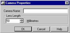

The define camera position function allows you to create and position a new camera. To use this tool, go to Radiance—>Analysis—>Define Camera Position. The Camera Properties Dialog Box then appears .
Figure 8. The Camera Properties Dialog Box and the camera icon
Enter a name for the camera and set the lens length. The lens length determines how long the zoom lens is. Smaller numbers make the lens shorter and therefore give a wider, farther away view. Conversely, larger numbers make the lens longer and will therefore give a narrower, closer view. After clicking OK you are brought back to the Graphic Editor window and prompted to give an insertion point, a rotation angle, and the height above the insertion point for the origin of the camera's view. If you enter a camera name that has already been used in the project, scenarios which use this camera will be changed to the new view parameters. The camera icon will then appear in your drawing at the insertion point. If the icon is either too small or too large, this can be adjusted in the preferences dialog box which can be accessed through the Radiance pulldown menu. For more on this, see Preferences.
To change the view of a camera first type view r and then type the name of the camera. The view of the camera will then appear with an outline representing the camera lens. Type dview. Several commands will appear at the command prompt that allow you to adjust your viewpoint in different ways. Consult the AutoCAD help section for detailed information on using these commands. Typically the Target and Zoom commands are very useful. Zoom allows you to zoom forwards and back. Target allows you to move your viewpoint target in all directions. Using these tools is difficult because your wireframe scene disappears while you make adjustments. After editing your camera view, hit enter at the dview prompt. Your new view will appear in wireframe. If you are satisfied with the view, you must save it with the ddview command. If you are unsatisfied with the new view you must return to the original view you started editing and then begin using the dview commands again. Once you are satisfied with the new view, type ddview, to save the new view. Click on New and then enter the same name as the camera view that you were originally editing. Entering the same name will allow you to select the original camera icon when starting a simulation, but with the updated view. Entering a new name will mean that you have to select the view name in the camera simulation setup dialog box because there won't be a picture of a camera representing your new view.
The camera view can also be changed more easily and quickly but not permanently in the rview program when you start a simulation. This is useful for checking your geometry or to find an ideal view.