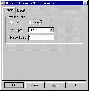
The General Preferences Dialog Boxis used to set the units (metric or imperial), unit size (meters, inches, etc.) of a drawing, and drawing "scale" for appropriate sizing of the Desktop Radiance library items. To use this tool go to RadianceàPreferences. There is an important relationship between the settings here and the units format of your graphic editor program. The most important relationship is that if the units display in your graphic editor are "Architectural", then you will want to choose "Imperial" and "Inches" in the Desktop Radiance General Preferences Dialog Box. See the note on Setting Up A DrawingSetting Up A Drawing for more explanation.
Sometimes when attaching or inserting a Radiance entity into your drawing, it will appear much smaller or much larger than you want it to be. This includes objects such as furnishings, luminaires, cameras, north arrows, and surface normal arrows. To fix this problem use the General Preferences tab dialog box. Before attaching the Radiance entity into your drawing, change the Symbol Scale value. To make an object larger, make the symbol scale value larger. To make an object smaller, make the symbol scale value smaller. For example, changing the value from 1 to 10 would make the object ten times as big as before. Whereas, to make an object smaller, changing the value from 1 to 0.1 would make the object one tenth as big as it was before. After changing the symbol scale value, then attach or insert the Radiance entity to your drawing.
Figure 22. General Preferencs Dialog Box
The Desktop Radiance Export Preferences Dialog Boxdetermines which entity types will be exported from your graphic editor for the simulation.
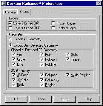
Figure 23. The Export Preferences Dialog Box
The layers options refer to the various layer settings in your Graphic Editor program. The Geometry option determines whether you want all geometry to be exported automatically for simulations or if you want to select particular Geometry yourself. Closed or Extruded 2D Geometry and 3D Geometry refer to types of geometry that can be included in simulations.