Setting up a camera
- Return to a plan view to make camera placement easier: plan ¿ ¿
- Define the camera position: Radiance—> Analysis—> Define Camera <select the origin of the view>
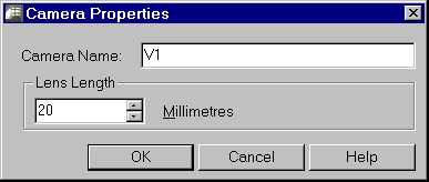
Figure 7. The Camera Properties dialog box.
- A Camera Properties dialog box appears (Figure 7): Enter the name of this camera such as "V1", enter the lens size in millimeters, ¿ A lens size of "20" mm is recommended for interior views. AutoCAD camera names are always in UPPERCASE and may not have any spaces.
- Enter the height of the camera: 5' ¿
- Make the camera we just created the current view: view R <V1>¿. The display should now change to a view from the inside of the camera looking in the specified direction. You can use the standard "dview" commands to alter the view if desired. If changes to this view are made, they need to be saved back to the view definition using the following two commands:
- Save the view: ddview <click on "new" button> V1 <click on "save view" button>, <click "yes" to overwrite>.
Note: Due to AutoCAD limitations, camera names will always be saved in ALL CAPS. Keep this in mind when selecting names for the cameras. Also note that plan and axonometric views will be displayed for the "default" view when the view "distance" parameter is zero. The default plan view is created at the origin (height=0), it will be coincident with any geometry also at the Z=0 plane and will be invisible in the Radiance simulation.
If all you see in the interactive render is beige, you are looking at the ground. This is remedied by using the AutoCAD "elevation" command. Set height of the default view above the Z=0 plane.


