![]() The Set View Dialog Boxsets specifications for the view or camera. The settings to specify include: Type, Size, Viewpoint, Clipping Plane, Direction, Up, and Offset.
The Set View Dialog Boxsets specifications for the view or camera. The settings to specify include: Type, Size, Viewpoint, Clipping Plane, Direction, Up, and Offset.
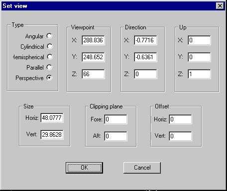
Figure 21. The Set View Dialog Box
Type:
Angular allows for a fisheye view of the model with a horizontal and vertical view size of up to 360 degrees.
Cylindrical gives a view of the model projected onto a horizontal cylinder as is used with quicktime VR applications.
Hemispherical fisheye views of the model with view size up to 180 degrees.
Parallel gives a flat elevation, section, or plan view of the model. View size is then interpreted in world units instead of degrees.
Perspective is a standard perspective view of the model from your viewpoint and allows for a view size of up to 179 degrees.
Size:
Horizontal sets the view angle for a perspective or fisheye view. For a parallel view it sets the width of the view in world units.
Vertical sets the height of the view window.
Viewpoint:
The X,Y,Z coordinates determine the focal point for a perspective view or the center point of a parallel projection image.
Clipping Plane:
This is a plane, perpendicular to your view direction, that cuts through and hides a portion of the image of your model. Fore and Aft refer to whether what is in front of or behind the plane, respectively, is hidden. The value that is entered in these boxes determines the distance from your viewpoint that the clipping plane is situated. If your image is in a fisheye view then the clipping plane is a clipping sphere and the value entered is the radius of the sphere. The center of the sphere being your viewpoint.
This tool is useful for viewing the inside of buildings by slicing off a wall on one side. A similar effect can be achieved with backface visibility.
Direction:
This tool defines the direction of the view vector that creates the view. The X,Y,Z boxes define a point that the view vector will pass through.
Up:
Up is defined by XYZ vectors, with the direction which appears to be the top of the computer screen being up. For example, for a view seen by a person standing and looking straight towards the horizon, the up is along the Z axis, and is defined by X=0 Y=0 Z=1.
Offset:
This tool offsets the view projection up, down, right, and left. A positive Horiz refers to a right offset. A positive Vert refers to a vertical offset.