Starting a rendering
Now that all surfaces have materials attached to them and you have a zone and view defined, you can start a Radiance simulation to produce a rendering.
- Select the surfaces to be included in the simulation and begin the geometry export: Radiance—> Simulation—> Camera <select the camera or click enter for the current view>¿ <select surface(s) to include or type "all"> ¿
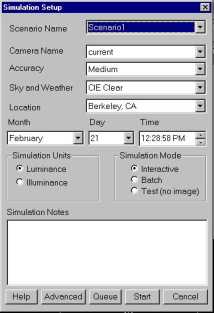
Figure 8. The Simulation Setup dialog box.
- Behind the scenes, Desktop Radiance has created a project directory with the same name as your drawing. If you rename or move your drawing, you will be prompted with various choices. If the project ID in the project database (dradproj.mdb) does not match the project ID stored in the drawing, you will be prompted to overwrite the existing project, use the existing project, or start a new one. The new button leads to a browse dialog box in which you can navigate your hard disk to find a suitable place for a new project directory or to open an existing project directory in a different location.
- The AutoCAD text window scrolls by with various messages, and the Simulation Setup dialog box appears (Figure 8).
- The scenario name at the top of the window shows the name for this scenario. Because this name is used as the base name for Radiance simulations, the name may only contain a limited set of valid characters: {a-z, A-Z, 0-9, _ }. Each time you initiate a simulation, you will be asked to provide a scenario name. The scenario keeps track of all the settings and used for each simulation.
- Select the camera from the list of names.
- The "Accuracy" setting only contains a "medium" setting for this version. However, you can adjust the rendering parameters under the "Advanced" button on the Simulation Setup dialog box to get a high quality rendering. The help document and online Desktop Radiance FAQs have more information on setting up the parameters.
- Select one of the pre-defined sky conditions, CIE Clear, CIE Overcast, CIE Intermediate, or CIE uniform. In later versions a custom sky selection will allow you to define a custom sky luminance distribution based on TMY weather data.
- The Location combo box lists a few predefined locations, or you can define your own locations by selecting "New…" from the bottom of the list. In the "location" dialog box, specify the city and state name, longitude, latitude and altitude from sea level. Click "OK" to save this location. The new location is then available for later simulation in this project and others.
- In the "Add New Location" dialog box (Figure 9), specify a city name. Country and state are optional fields. Then input the latitude and longitude of the location you want to simulate and pick a corresponding time zone from the pull down menu. Be aware of whether your time zone is observing Daylight Saving Time. If not listed, pick "other" from the list and then enter the Standard Meridian for that location. See the Desktop Radiance User Manual for more information.
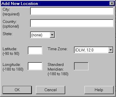
Figure 9. The Add New Location Dialog box
- Back in the Simulation Setup dialog box, select the Month, Day, and Time for the simulation.
- Select the desired simulation quantity (luminance or illuminance) and select "interactive".
- Click the "start" button to begin the simulation. This initiates the synchronization of your project files with the contents of the drawing.
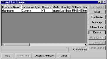
Figure 10. The Simulation Manager dialog box.
- The Simulation Manager dialog box (Figure 10) should appear momentarily. Wait for the interactive window to appear. This can take a few seconds for small scenes or up ten minutes for very complex scenes.
- Then a window called "rview" should appear and begin to refine an image over a period of less than a minute. If you have many glazings, light sources, or a very complex scene, this could take a bit longer.
Note: Rview is an interactive renderer suitable for previewing and validating your model, but not for generating high quality renderings. For high quality renderings, use batch mode instead.
- After tracing the first several dozen rays, the image will be automatically exposed to the average for this view. (See Figure 11)
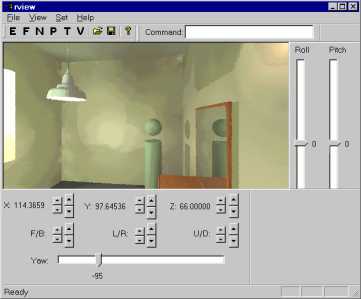
Figure 11. The interactive rendering window.
- Visibility and placement of the toolbars is controlled with the "view" menu. Different views of your scene can be created by manipulating the various toolbar widgets. F/B, L/R, ad U/D stand for Front/Back, Left/Right, and Up/Down position displacements of the viewpoint. If the toolbars are not visible, use the view menu to display them.
- To save a view for subsequent renderings use the File—> Append View to View File or Append View to RIF File commands. Adding a view to an existing View file will overwrite the file. Adding a view to a RIF file will allow that view to be accessible from the Simulation Setup dialog box for subsequent simulations based upon the original scenario in which the rendering was created.
Note: View file names cannot contain spaces.
- If you would like to save a draft version of your rendering, the File—> Save menu command can be used to save the drawing under the default name. Note that the naming convention for images is "Scenenarioname_viewname.pic." You can save the image with a different name, but the Simulation Manager will not be able to automatically display it using the "Display/Analyze" button. You will need to open the Winimage program, select File—> Open, and navigate to find the name of your image. To close rview, either type "quit" in the rendering window or click the "close button (x).
Note: Rview will always prompt you to save the image when closing even if the image has already been saved before. This is because rview does not stop rendering once you save the image but continues to refine it until it is either finished (status bar near bottom of screen reads "ready") or the application is closed. Make sure that you are saving the image in your project directory. Window 98 and Windows 2000 default to the "My Documents" folder.
- You will now return to the Simulation Manager dialog box. The scenario will be indicated as "finished."
- You can create a new scenario based upon the previous one by clicking the "Duplicate" button.
- The Simulation Setup dialog will appear. Here you can make changes to the settings. For higher quality renderings, you will want to render an image to a file in "batch" mode. Click the Queue button to add this scenario to the simulation manager queue. This process can be repeated for as many scenarios as desired To manually start any of the queued scenarios, select the desired scenario by clicking on its line and click "start". In future versions of Desktop Radiance, the Simulation Manager will provide a means of managing simulations that are processing and scheduling processes to begin when others have finished.


